
MPI 540-PV
Catalog index: WMGBMPI540PV
Multi-Function Meter Of Electrical System Parameters
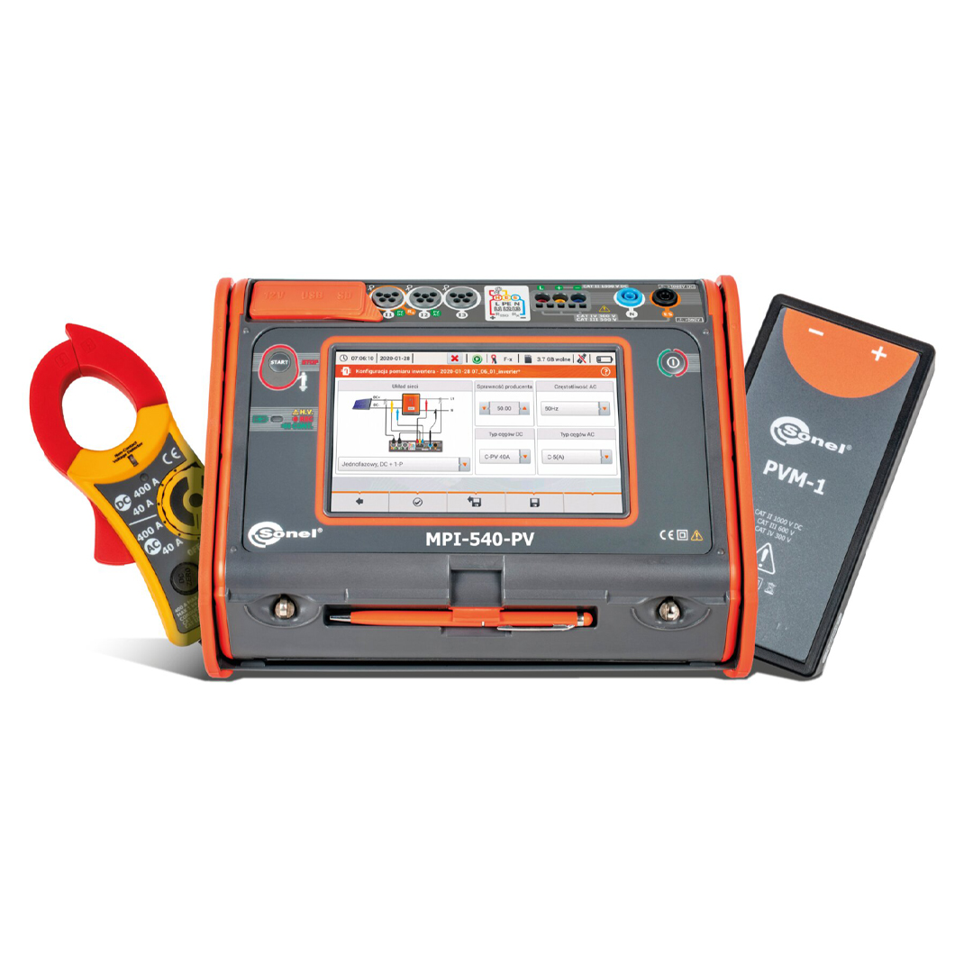
The multifunctional meter of electrical installation parameters Sonel MPI-540-PV is an advanced tool created in particular for measuring parameters of photovoltaic installations. With the use of one device, it is possible to carry out a whole range of tests on the DC and AC sides in accordance with the guidelines of the EN 62446 standard. In addition, the Sonel MPI-540-PV is also used to carry out all measurements to determine the safety condition of domestic as well as industrial electrical installations. The presented meter is a device with advanced capabilities, dedicated to specialists operating in the installation and electrical industry.
When measuring the parameters of a photovoltaic installation, the meter automatically recalculates the parameters to the STC (Standard Test Conditions) reference conditions. Measurements of voltages, currents and power on the AC and DC side of the inverter will verify its efficiency. After transferring the data stored in the meter's memory to the Sonel Reports PLUS program, it is possible to generate a report of photovoltaic installation parameters.
In order to automate measurements, the Sonel MPI-540-PV meter has been additionally enriched with the function of testing residual current devices in Auto mode. The instrument also has measurement sequences pre-programmed by the manufacturer (so-called autotests), which can be extended with own sequences if necessary. The capabilities and functionality of the meter will be additionally enhanced by a suitably selected additional accessory, e.g. the AutoISO-1000C adapter, which enables the automatic measurement of insulation resistance of 3-, 4- and 5-core cables.
Much more than a multifunctional meter
- The largest touch screen on the market (7”) – remarkable ergonomics and ease of use
- Removable microSD memory card – easy increase of memory capacity
- Li-Ion battery – longer operation of the meter
- Measurement of photovoltaic installations according to EN 62446 standard
- Cooperation with solar radiation and temperature meter
- Photovoltaic installation test report with Sonel Reports PLUS software
- Three-phase power recorder – advanced power quality diagnostics
- Real time display of network parameters – immediate evaluation of the test site conditions
- Parameters measured in accordance to class S of EN 61000-4-30 standard – high accuracy of measurements
- Energy cost calculator – quick evaluation of potential savings
- Measurement of all parameters related to earthing and protection against electric shock – one device instead of several
- Quick measurement of the fault loop impedance in networks secured with RCD without triggering (up to several seconds) – time saver
- Auto measurements – the ability to perform automatic measurements in sequence – simplified measurements
- Fast path from measurements to report – time saver
Features
The meter has above-average functionality. It combines the measuring capabilities of several devices, while ensuring equally good accuracy.
- The MPI-540-PV instrument can measure photovoltaic installations in accordance with the EN 62446 standard:
- continuity of protective and equipotential bondings,
- earth resistance,
- insulation resistance on the DC side,
- open circuit voltage UOC,
- short circuit current ISC,
- work currents and powers on both DC and AC side,
- inverter efficiency.
- MPI-540-PV can record 50/60 Hz power quality parameters in accordance to S class of EN 61000-4-30:
- voltage L1, L2, L3, – average values in the range up to 500 V,
- L1, L2, L3 currents, – average values, current measurement in the range up to 3 kA (depending on the current probes used),
- frequency in the range of 40 Hz – 70 Hz, » active (P), reactive (Q) and apparent (S) power,
- power factor (PF), cosφ, tanφ,
- harmonics (up to 40th for voltage and current),
- total harmonic distortion (THD) for current and voltage,
- recording of events for current and voltage,
- energy flow – 4 quadrants.
- MPI-540-PV can be used for all measurements for commissioning of electrical installations in accordance with applicable regulations:
- short circuit loop impedance (also in circuits secured with RCDs),
- RCD parameters,
- insulation resistance,
- earth resistance (4 measurement methods + soil resistivity measurement),
- continuity of protective and equipotential bondings,
- light intensity measurement,
- phase sequence test,
- motor rotation direction test
Automatic installation safety test
MPI-540 / MPI-540-PV allow safety control of residential, commercial and industrial electrical installations. Measurements can be easily automated with:
- auto mode of residual current devices (RCD) tests,
- auto measurements – freely configurable measuring sequences,
- AutoISO-1000C adapter for automatic insulation resistance test of 3-, 4- and 5-conductor cables, without switching.
Photovoltaics under supervision
MPI-540-PV is an extremely universal meter, designed in particular for testing photovoltaic installations. The device allows a complete set of tests on the DC and AC side – in accordance with the guidelines of EN 62446 standard.
Measuring parameters related to the photovoltaic installation, the instrument will automatically convert them to the STC (Standard Test Conditions) reference conditions. Measurements of voltage, current and power on the AC and DC side of the inverter allow to verify its efficiency. Sonel Reports PLUS software enables creating PV installation test report with measurement results saved meter’s in memory.
Three-phase power quality recorder
The device has a three-phase power quality recorder with the LIVE mode view and the possibility to register electrical network parameters such as voltage, current, power, harmonics and THD. The meter enables reading of selected parameters and their graphic presentation on the screen in real time. These parameters are measured and displayed concurrently with the recording on the memory card. In the LIVE mode, the user can see:
- voltage and current waveforms (oscilloscope),
- voltage and current timeplots,
- a phasor graph,
- display of multiple parameters in tabular form,
- spectrum graph of current and voltage harmonics.
Ease of reading
The device is equipped with a color TFT LCD touch screen with a resolution of 800x480 pixels and a diagonal of 7”, which allows for convenient operation and easy reading of parameters and plotted waveforms. This screen size enables displaying more information, available at any time of use. The interface is visible in all conditions – also thanks to the appropriate size of displayed symbols. Included stylus allows to work also with dielectric gloves.
Built-in help system
The device has built-in help screens with measurement diagrams. Thanks to this you can easily and quickly check and make sure how to connect to a given system depending on the type of performed measurement.
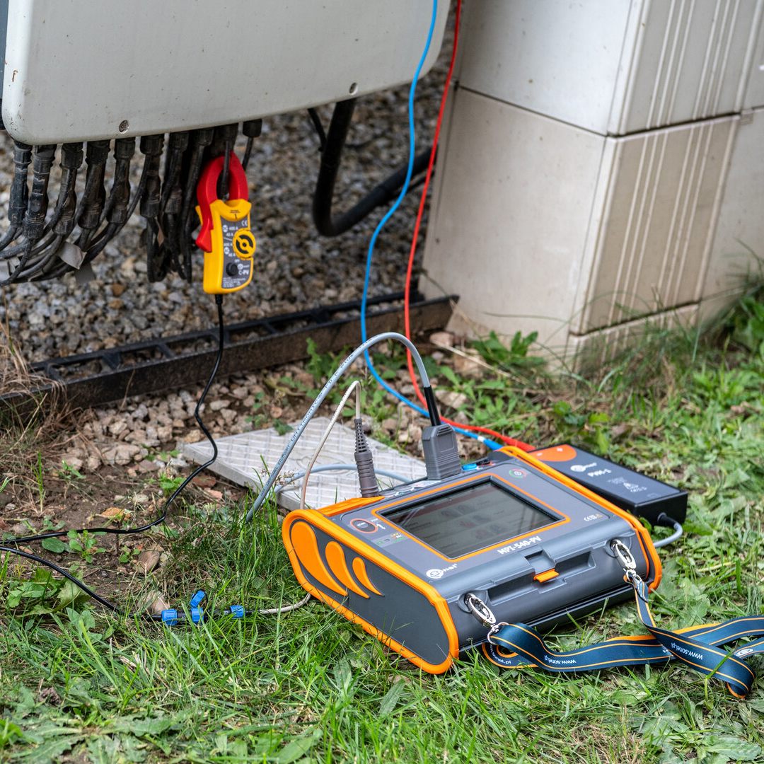
Increased resistance to environmental conditions
The MPI-540-PV meter will cope well in difficult environmental conditions. Protection against penetration of dust and water is ensured by a unique housing with a level of protection IP51. It is resistant to mechanical damage, and a special design allows you to easily protect the touch screen by shielding using the cover of the meter. In addition to the fact that it protects against damage, it also allows you to conveniently carry and use the device in different positions.
Communication and software
A very strong feature of the device is the multitude of communication interfaces and cooperation with external software. You can easily transfer measurement data to your computer via USB port, removable SD memory card, or wireless communication (Bluetooth*, Wi-Fi ). In order to generate a report on measurements for electric shock protection, use Sonel Reports PLUS software. Saving the downloaded data to the simplest formats and printing is provided by free Sonel Reader software. The specialized, free Sonel Analysis software is used to read and analyze data from the power quality recorder.
Specification
Electrical Installation Parameters
| Measurement functions | Measurement range | Display range | Resolution | Accuracy |
|---|---|---|---|---|
| Fault loop impedance | ||||
| Fault loop ZL-PE, ZL-N, ZL-L | 0.13 Ω…1999.9 Ω acc. to IEC 61557 | 0.00 Ω…1999 Ω | from 0.001 Ω | ±(5% m.v. + 30 digits) |
| Fault loop ZL-PE in RCD mode | from 0.50 Ω…1999 Ω acc. to IEC 61557 | 0.00 Ω…1999 Ω | from 0.01 Ω | from ±(6% m.v. + 5 digits) |
| Measurements of RCD parameters | ||||
| RCD tripping test and measurement of tripping time tA measuring current 0.5 IΔn, 1 IΔn, 2 IΔn, 5 IΔn | ||||
| general and short-time delay RCD | 0 ms…300 ms | 0 ms…300 ms | 1 ms | from ±(2% m.v. + 2 digits) |
| selective RCD | 0 ms…500 ms | 0 ms…500 ms | 1 ms | from ±(2% m.v. + 2 digits) |
| Measurement of RCD tripping current IA measuring current 0 0.2 IΔn…2.0 IΔn | ||||
| for sinusoidal residual current (AC type) | 3.3 mA…1000 mA | 3.3 mA…1000 mA | from 0.1 mA | ±5% IΔn |
| for unidirectional residual current and unidirectional with the 6 mA DC bias (type A) | 3.5 mA…700 mA | 3.5 mA…700 mA | from 0.1 mA | ±10% IΔn |
| for direct residual current (type B)) | 2.0 mA…1000 mA | 2.0 mA…1000 mA | from 0.1 mA | ±10% IΔn |
| Earth resistance | ||||
| 3- and 4-pole method | from 0.50 Ω…1.99 kΩ acc. to IEC 61557-5 | 0.00 Ω…1,99 kΩ | from 0.01 Ω | from ±(2% m.v. + 3 digits) |
| 3-pole + clamp method | 0.00 Ω…1.99 kΩ | 0.00 Ω…1.99 kΩ | from 0.01 Ω | from ±(2% m.v. + 4 digits) |
| 2-Pole method | 0.00 Ω…99.9 kΩ | 0.00 Ω…99.9 kΩ | from 0.01 Ω | from ±(10% m.v. + 4 digits) |
| Resistance-to-earth | 0.0 Ω m…99.9 kΩm | 0.0 Ωm…99.9 kΩm | from 0.1 Ωm | Depending on accuracy of RE measurement |
| Insulation resistance | ||||
| Measuring voltage 50 V | 50 kΩ…250 MΩ acc. to IEC 61557-2 | 0 kΩ…250 MΩ | from 1 kΩ | from ±(3% m.v. + 8 digits) |
| Measuring voltage 100 V | 100 kΩ…500 MΩ acc. to IEC 61557-2 | 0 kΩ…500 MΩ | from 1 kΩ | from ±(3% m.v. + 8 digits) |
| Measuring voltage 250 V | 250 kΩ…999 MΩ acc. to IEC 61557-2 | 0 kΩ…999 MΩ | from 1 kΩ | from ±(3% m.v. + 8 digits) |
| Measuring voltage 500 V | 500 kΩ…2.00 GΩ acc. to IEC 61557-2 | 0 kΩ…2.00 GΩ | from 1 kΩ | from ±(3% m.v. + 8 digits) |
| Measuring voltage 1000 V | 1000 kΩ…4.99 GΩ acc. to IEC 61557-2 | 0 kΩ…9.99 GΩ | from 1 kΩ | from ±(3% m.v. + 8 digits) |
| Resistance of protective conductors and equipotential bondings | ||||
| Measurement of resistance of protective conductors and equipotential bondings with ±200 mA current | 0.12 Ω…400 Ω acc. to IEC 61557-4 | 0.00 Ω…400 Ω | from 0.01 Ω | ±(2% m.v. + 3 digits) |
| Measurement of resistance with low current | 0.0 Ω…1999 Ω | 0.0 Ω…1999 Ω | from 0.1 Ω | ±(3% m.v. + 3 digits) |
| Light intensity | ||||
| Measurement in luxes (lx) | 0 lx…399.9 klx | 0 lx…399.9 klx | from 0.001 lx | from ±(2% m.v. + 5 digits) |
| Measurement in feet-candles (fc) | 0 fc…39.99 kfc | 0 fc…39.99 kfc | from 0.001 fc | from ±(2% m.v. + 5 digits) |
| Phase sequence indication | in the same direction (correct), opposite direction (incorrect), UL-L voltage: 95 V…500 V (45 Hz…65 Hz) |
“m.v.” – measured value
Specifications – 3-phase power quality recorder
The device is designed to work with mains:
- with nominal frequency 50/60 Hz
- with nominal voltage: 64/110 V, 110/190 V, 115/200 V, 127/220 V, 220/380 V, 230/400 V, 240/415 V, 254/440 V, 290/500 V
- DC networks
Supported systems:
- single-phase
- split-phase with common N
- three-phase – WYE with and without N conductor
- three-phase – Delta
| Parameter | Measuring range | Max. resolution | Accuracy |
|---|---|---|---|
| Alternating voltage (TRMS) | 0.0…500 V | 0.01% Unom | ±0,5% Unom |
| Alternating current (TRMS) | depending on clamp* | 0.01% Inom | ±2% m.v. if m.v. ≥ 10% Inom, ±2% Inom if m.v. < 10% Inom , (error does not account for clamp error) |
| Frequency | 40.00…70.00 Hz | 0.01 Hz | ±0.05 Hz |
| Active, reactive, apparent and distortion power | depending on configuration (transducers, clamps) | 4 significant digits | depending on configuration (transducers, clamps) |
| Active, reactive and apparent energy | depending on configuration (transducers, clamps) | 4 significant digits | as power error |
| cosφ and power factor (PF) | 0.00…1.00 | 0.01 | ±0.03 |
| Harmonics | |||
| Voltage | as for alternating voltage True RMS | as for alternating voltage True RMS | ±5% m.v. if m.v. ≥ 3% Unom, ±0,15% Unom if m.v. < 3% Unom |
| Current | as for alternating current True RMS | as for alternating current True RMS | ±5% m.v. if m.v. ≥ 10% Unom, ±0,5% Unom if m.v. < 10% Unom |
| THD | |||
| Voltage | 0.0…100.0% (relative to RMS value) | 0.1% | ±5% |
| Current | 0.0…100.0% (relative to RMS value) | 0.1% | ±5% |
| Unbalance factor | 0.0…10.0% | 0.1% | ±0.15% (absolute error) |
AC currentmeasurment (True RMS) with clamp
| C-4A | C-5A | C-6A | C-7A | F-1A | F-2A | F-3A | |
|---|---|---|---|---|---|---|---|
| Rated current | 1000 A AC | 1000 A AC 1400 A DC |
10 A AC | 100 A AC | 3000 A AC | 3000 A AC | 3000 A AC |
| Frequency | 30 Hz…10 kHz | DC…5 kHz | 40 Hz…10 kHz | 40 Hz…1 kHz | 40 Hz…10 kHz | 40 Hz…10 kHz | 40 Hz…10 kHz |
| Max. diameter of measured conductor | 52 mm | 39 mm | 20 mm | 24 mm | 380 mm | 250 mm | 140 mm |
| Minimum accuracy | ≤0,5% | ≤1,5% | ≤1% | 0,5% | 1% | 1% | 1% |
| Battery power | – | √ | – | – | – | – | – |
| Lead length | 2.2 m | 2.2 m | 2.2 m | 3 m | 2.5 m | 2.5 m | 2.5 m |
| Measurement category | IV 300 V | IV 300 V | IV 300 V | III 300 V | IV 600 V | IV 600 V | IV 600 V |
| Ingress protection | IP40 | IP40 | IP40 | IP40 | IP67 | IP67 | IP67 |
Specifications – photovoltaic installation parameters
| Measurement functions | Display range | Resolution | Accuracy |
|---|---|---|---|
| Open circuit voltage UOC | 0.0 Ω…1000 V | from 0.1 V | from ±(3% m.v. + 2 digits) |
| Short circuit current ISC | 0.00 Ω…20.00 A | 0.1 A | ±(3% m.v. + 0.10 A) |
Reviews
There are no reviews yet.